Pages

Feb 23, 2008

Modifying Objects

Modifying Objects
Introduction

AutoCAD drawings are rarely completed simply by drawing lines, circles etc. Most likely you will need to Modify these basic drawing objects in some way in order to create the image you need. AutoCAD provides a whole range of modify tools such as Move, Copy, Rotate and Mirror. As you can see, the command names are easily understandable. However, the way these commands work is not always obvious. This tutorial is designed to show you how all of the Modify commands work. If you just need information quickly, use the QuickFind toolbar below to go straight to the information you need or select a topic from the contents list above.


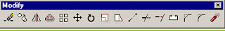
As is usual with AutoCAD, the Modify tools can be accessed in one of three ways, from the keyboard, from the pull-down menu and from the toolbar. All of the Modify tools are available from the Modify pull-down and the Modify toolbar. In each section below, the toolbar, pull-down and keyboard options are given. The method you choose is entirely up to you. Ultimately you will use the method that you feel most comfortable with or the one you find most efficient. AutoCAD allows great flexibility and there aren't any right or wrong ways of working. That said, it should be pointed out that the use of toolbars in AutoCAD is almost always quicker than any other method.

The Modify toolbar is usually displayed by default but if it is not already displayed, you can display it using the TOOLBAR command, ViewToolbars… from the pull-down menu. When the Toolbar dialogue box (shown above) appears, simply check the box next to "Modify" in the toolbars list. Many AutoCAD users work with the Modify toolbar permanently docked on their screen because it gives one-click access to all of the commands, making the drawing process much more efficient.

1. The Erase Command
2. The Copy Command
3. The Mirror Command
4. The Offset Command
5. The Array Command
6. The Move Command
7. The Rotate Command
8. The Scale Command
9. The Stretch Command
10. Stretching with Grips
11. The Lengthen Command
12. The Trim Command
13. The Extend Command
14. The Break Command
15. The Chamfer Command
16. The Fillet Command
17.Tips & Tricks Tips

Tips & TricksHot Tips

Tips & TricksHot Tips

* Always look at the command line for guidance when you are learning new AutoCAD commands. The command line will prompt you for information and this is the easiest way to find out how a new command works. This is especially true for the more complicated commands like Trim and Extend.

* The command line window displays 3 lines of text by default. You can change this by clicking and dragging the top of the window frame. When you are starting with AutoCAD you may like to see more than 3 lines. The illustration below shows the command line window increased in size to 6 lines.

* The command line can also be displayed as a floating text window. The AutoCAD text window is displayed by pressing the F2 key on the keyboard. See Function Keys on the Drawing Aids tutorial for more details.

* You can control the way text is mirrored using the MIRRTEXT variable.

* Fillet 0You can use the Fillet command with a radius of zero to trim intersecting lines back to their intersection. Of course, you could also achieve this effect with the Trim command but if you have a number of operations to complete, the Fillet method is much quicker.

* When using the Trim and Extend commands, hitting Return when prompted to "Select cutting edges" and "Select boundary edges" respectively will automatically select all valid cutting or boundary edges on the screen. This can be a real time saver if you have a complicated set of edges to select.

The Fillet Command

Toolbar Modify Fillet
Pull-down ModifyFillet
Keyboard FILLET short-cut F

The Fillet command is a very useful tool which allows you to draw an arc between two intersecting lines or adjacent polyline segments. You first need to use the command to set the required radius and then a second time to select the two lines.

Command Sequence

Command: FILLET
Current settings: Mode = TRIM, Radius = 10.0000
Select first object or [Polyline/Radius/Trim]: R
Specify fillet radius <10.000>: 25
Select first object or [Polyline/Radius/Trim]: (pick P1)
Select second object : (pick P2)

The Fillet command can also be used to fillet arcs and circles. The "Polyline" option also allows you to fillet all vertices of a polyline with a single command. It's worth experimenting with this command, it can save you lots of time and enables you to construct shapes which otherwise would be quite difficult.

For example, you can easily create the lozenge shape shown on the right from a simple rectangle. Since AutoCAD rectangles are just closed polylines, you can use the Polyline option of the Fillet command to fillet all polyline vertexes simultaneously. Try this for yourself; draw a rectangle and then follow the command sequence below.


Command Sequence

Command: FILLET
Current settings: Mode = TRIM, Radius = 10.0000
Select first object or [Polyline/Radius/Trim]: P
Select 2D polyline: (pick P1)
4 lines were filleted

Tip: Make sure that the radius you specify will fit the objects you select, otherwise the fillet command will not work.

The Chamfer Command

Toolbar Modify Chamfer
Pull-down ModifyChamfer
Keyboard CHAMFER short-cut CHA

The Chamfer command enables you to create a chamfer between any two non-parallel lines as in the illustration below or any two adjacent polyline segments. Usually, the Chamfer command is used to set the chamfer distances before drawing the chamfer. Follow the command sequence below where the chamfer distances are changed to 20 before the chamfer is made.


Command Sequence

Command: CHAMFER
(TRIM mode) Current chamfer Dist1 = 10.0000, Dist2 = 10.0000
Select first line or [Polyline/Distance/Angle/Trim/Method]: D (to set distances)
Specify first chamfer distance <10.0000>: 20 (enter required distance)
Specify second chamfer distance <20.0000>: Return(first distance value or enter a different value)
Select first line or [Polyline/Distance/Angle/Trim/Method]: (pick P1)
Select second line: (pick P2)
The chamfer is made and the command ends.

Notice from the command sequence that there are a number of options which can be used to control the way the Chamfer command behaves. The Polyline option can be used to chamfer all vertexes of a polyline simultaneously. The Distance option allows you to specify the two chamfer distances. Angle allows the angle between the first line and the chamfer to be specified. Trim is used to control whether the original lines are trimmed to the chamfer or remain as they are. Finally, Method is used to toggle the command between Distance and Angle mode. When Angle mode is used, the chamfer is defined using one distance and an angle rather than two distances.

The Break Command

Toolbar Modify Break
Pull-down ModifyBreak
Keyboard BREAK short-cut BR

The Break command enables you to break (remove part of) an object by defining two break points. In the illustration below, a corner of a rectangle has been removed. The Break command can be used with lines, polylines, circles, arcs ellipses, splines, xlines and rays. When you break an object, you can either select the object using the first break point and then pick the second break point, or you can select the object and then pick the two break points.


Command Sequence

Command: BREAK
Select objects: (select the object using the first break point, P1)
Specify second break point or [First point]: (pick the second break point, P2)
The section of the object is removed and the command ends.

Sometimes you may want to select the object first and then specify the two break points. If this is the case, use the "First point" option to specify the first break point. By default, AutoCAD assumes that the point used to select the object is the first break point. This is often confusing for new users.

It may sometimes be necessary to break a line into two without removing any part of it. In this case, simply pick the first and second break points in the same position.

The Extend Command

Toolbar Modify Extend
Pull-down ModifyExtend
Keyboard EXTEND short-cut EX

This command extends a line, polyline or arc to meet another drawing object (known as the boundary edge). In the illustration on the right, two lines (red) are extended to meet another line (cyan) which forms the boundary edge. This command works in a similar way to the Trim command, described above. Two selections are made, one for the boundary edge(s) and one for the object(s) to extend.

Lines and other objects can be extended in one of two directions. In the illustration on the right, the red line could be extended either to the right or to the left. You can tell AutoCAD in which direction to extend by picking a point to the right or left of the midpoint respectively. AutoCAD does not intuitively know where the boundary edge lies so you must explicitly indicate the direction of extension by picking either one side or other of the midpoint.

Draw the lines as shown in the illustration and follow the command sequence below.

Command Sequence

Command: EXTEND
Current settings: Projection=UCS Edge=None
Select boundary edges ...
Select objects: (select the boundary edge, P1)
Select objects: Return(to end boundary edge selection)
Select object to extend or shift-select to trim or [Project/Edge/Undo]: (pick the object which you want to be extended, P2)
Select object to extend or shift-select to trim or [Project/Edge/Undo]: (pick another object which you want to be extended, P3)

Select object to extend or shift-select to trim or [Project/Edge/Undo]: Return(to end)

Sometimes you may get the message "Object does not intersect an edge" or "No edge in that direction". If this happens it means that you are either picking the wrong end of the object or the object you are trying to extend will not meet the boundary edge. The solution is either to pick near the end you want to extend or to move the boundary edge so that the extended line will intersect with it.

Using Edgemode
If the line you are trying to extend does not intersect with the boundary line, you can use the "Edge" option to toggle Edgemode to "Extend" (the default is "No Extend"). When the Extend command is set to Extend Mode, the objects being extended will extend to an imaginary line through the boundary edge, irrespective of whether the extended object actually intersects with the boundary edge. This is particularly useful and can save lots of time.

The illustration on the left shows the result of extending a line (red) to a boundary edge (cyan) with Edgemode set to "Extend". The same process would have resulted in an error message if Edgemode had been set to "No Extend". To get a better understanding of how this works, draw the two lines as shown in the illustration and try to extend them using the default settings. When you have done that, follow the command sequence below.

Command Sequence (Edgemode)

Command: EXTEND
Select boundary edges: (Projmode = UCS, Edgemode = No extend)
Select objects: (select the boundary edge, P1)
Select objects: Return (to end boundary edge selection)
Select object to extend or shift-select to trim or [Project/Edge/Undo]: E (to use the Edge option)
Enter an implied edge extension mode [Extend/No extend] : E (to set Edgemode to Extend)
Select object to extend or shift-select to trim or [Project/Edge/Undo]: (pick the object to be extended, P2)
Select object to extend or shift-select to trim or [Project/Edge/Undo]: Return (to end)

Notice that the current value of Edgemode is always displayed on the command line when you start the Extend command. The Edge option can also be used with the Trim command to enable trimming to cutting edges which do not actually intersect the object to trim. Edgemode is a system variable, so any change to its value will affect both the Trim and Extend commands.

Shift Selection with Trim & Extend

You may have noticed during the command sequences for the Trim and Extend commands that you have the option to "shift-select". This feature is new to AutoCAD 2000i and it enables you to extend while using the Trim command and to trim while using the Extend command. These two commands are very closely related and you often need to trim and extend objects at the same time. If you are a beginner with AutoCAD it may be a good idea to avoid this feature initially, the Trim and Extend commands can be tricky to get to grips with in any case. However, do remember this feature because it is a great time saver.

The Trim Command

Toolbar Modify Trim
Pull-down ModifyTrim
Keyboard TRIM short-cut TR

The Trim command can be used to trim a part of an object. In order to trim an object you must draw a second object which forms the "cutting edge". Cutting edges can be lines, xlines, rays, polylines, circles, arcs or ellipses. Blocks and text cannot be trimmed or used as cutting edges. The illustration on the right shows the Trim command in action. The red square and circle have been drawn using the Polygon and Circle commands respectively. In order to trim these objects, a line has been drawn (cyan in the illustration), this forms the cutting edge. The Trim command, unlike most other modify commands requires that two separate object selections are made. The cutting edges are selected first (there can be one or more) and then the objects to be trimmed are selected. In the example above, the line is selected first because it forms the cutting edge and then the square and circle are selected.

The Trim command is slightly more complicated than many other modify commands. To get a better understanding of how it works, draw a square, circle and line as illustrated above and then follow the command sequence below. Don't forget to watch the AutoCAD command line at each stage of the process.

Command Sequence

Command: TRIM
Current settings: Projection=UCS Edge=None
Select cutting edges ...
Select objects: (select the cutting edge, P1)
Select objects: Return (to end cutting edge selection)
Select object to trim or shift-select to extend or [Project/Edge/Undo]:(pick the part of the square which you want to trim, P2)
Select object to trim or shift-select to extend or [Project/Edge/Undo]: (pick the circle, P3)
Select object to trim or shift-select to extend or [Project/Edge/Undo]: Return (to end)

Notice that at each trimming step you are given the option to undo the previous trim. This can be very useful if you inadvertently pick the wrong object.

In the above example, when the objects were trimmed, both pick points were made to the right of the cutting edge, resulting in the removal of that part of the objects to the right of the cutting edge. Obviously, the portion of square and circle to the left of the cutting edge could have been removed by picking to the left of the cutting edge. Also, you may not have noticed it, but by trimming a circle you have created an Arc object. This makes no visible difference but the object type has changed.

The Lengthen Command

Toolbar Modify Lengthen
Pull-down ModifyLengthen
Keyboard LENGTHEN short-cut LEN

The Lengthen command can often be used instead of either the Trim or Extend commands. Indeed the end result is exactly the same. The Lengthen command can be used to either lengthen or shorten Lines, Arcs, open Polylines, elliptical Arcs and open Splines without the use of cutting or boundary edges.

Command Sequence

Command: LENGTHEN
Select an object or [DElta/Percent/Total/DYnamic]: DY
Select an object to change or [Undo]: (select a line or arc)
Specify new end point: (pick new end point)
Select an object to change or [Undo]: Return (to end)

The command sequence above demonstrates the use of the Dynamic Lengthen option which is probably the most useful for general purpose drafting. However, the other options are worth getting to know because they can save lots of time and effort.

The Total option allows you to change the total length of a line to any value that you specify. The Percent option allows you to change a line length using a percentage. For example, a value of 50 will result in a line one half the length of the original and a value of 200 will result in a line twice the length of the original. The Delta option can be used to extend or reduce the endpoint of a line by a given distance. The endpoint affected by the change is the one closest to the pick point when the object selection is made.

Stretching with Grips

Although the Stretch command can be very useful, it has largely been superseded by the use of "Grips" which allow this sort of modification to be made much more intuitively.


To stretch an object using grips, simply select the object by clicking on it (you can do this without starting a command). The object becomes highlighted and small square grips appear at each vertex and various snap points, depending upon the object type. Click a grip to activate it and click again to reposition it. When you have completed your modifications, use the Escape key (Esc) at the top left of your keyboard to deselect the object and release grips.

The Stretch Command

Toolbar Modify Stretch
Pull-down ModifyStretch
Keyboard STRETCH short-cut S

The Stretch command can be used to move one or more vertices of an object whilst leaving the rest of the object unchanged. In the example below, a rectangle has been stretched by moving one vertex to create an irregular shape.

Command Sequence

Command: STRETCH
Select objects to stretch by crossing-window or crossing-polygon...
Select objects: (pick first point of crossing window)
Specify opposite corner: (pick second point of window)
Select objects: Return(to end selection)
Specify base point or displacement: (pick base point)
Specify second point of displacement: (pick second point)

To select vertices to stretch, you must use a crossing window or polygon. See the "Object Selection" tutorial for details of these selection methods.

The Scale Command


Toolbar Modify Scale
Pull-down ModifyScale
Keyboard SCALE short-cut SC
The Scale command can be used to change the size of an object or group of objects. You are prompted for a pick point about which the selection set will be scaled. Scaling can then be completed by picking a second point (not always easy because it can sometimes be difficult to precisely control the scaling) or by entering a scale factor at the keyboard. For example a scale factor of 2 will double the size of the objects in the selection set and a factor of 0.5 will half them.

Command Sequence
Command: SCALE
Select objects: (pick objects to be scaled, P1)
Select objects: Return(to end selection)
Specify base point: (pick base point, P2)
Specify scale factor or [Reference]: (pick second point, P3 or enter scale factor)

In the example shown above, the original tree symbol has been enlarged by dynamically scaling it using pick points to determine the change in scale. If you want to scale an object precisely, it is much easier to enter a scale factor using the keyboard.

Note that the position of the new sized tree symbol is determined by the location of the base point. The base point, P2 has been picked to the upper right of the centre of the tree which resulted in the centre of the tree shifting to a lower left position. If the base point had been picked in the centre of the tree symbol, the tree would have remained in the same position. In theory the base point can be any point in the drawing area but for ease of control it is best to choose a known point so that the results are obvious.

The Rotate Command


Toolbar Modify Rotate
Pull-down ModifyRotate
Keyboard ROTATE short-cut RO

The Rotate command allows an object or objects to be rotated about a point selected by the user. AutoCAD prompts for a second rotation point or an angle which can be typed at the keyboard.

Command Sequence

Command: ROTATE
Current positive angle in UCS: ANGDIR=counterclockwise ANGBASE=0
Select objects: (pick object to rotate, P1)
Select objects: Return(to end selection)
Specify base point: (pick base point, P2)
Specify rotation angle or [Reference]: (pick second point, P3 or enter angle)

Remember, by default, AutoCAD angles start at 3 o'clock and increase in an anti-clockwise direction. The "ANGDIR" and "ANGBASE" variables remind you of this. If you want to rotate in a clockwise direction you can enter a negative angle by using a minus sign.

Note:
You can change the angle direction and the base angle using the Units command, FormatUnits… from the pull-down menu. Click the "Clockwise" check box to change the direction and click the "Direction…" button to set the base angle.

The Move Command

Toolbar Modify Move
Pull-down ModifyMove
Keyboard MOVE short-cut M

The Move command works in a similar way to the Copy command except that no copy is made, the selected object(s) is simply moved from one location to another.

Command Sequence

Command: MOVE
Select objects: (pick object to move, P1)
Select objects: Return (to end selection)
Specify base point or displacement: (pick P2)
Specify second point of displacement or : (pick P3)

Note that as with the Copy command, the two pick points, P2 and P3 are used only to indicate the distance and direction of movement.
Google Groups
Subscribe to design helper
Email:
Visit this group