
| Toolbar | Modify | ||
| Pull-down | Modify | ||
| Keyboard | CHAMFER | short-cut | CHA |
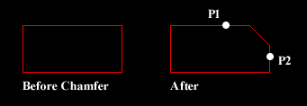
The Chamfer command enables you to create a chamfer between any two non-parallel lines as in the illustration below or any two adjacent polyline segments. Usually, the Chamfer command is used to set the chamfer distances before drawing the chamfer. Follow the command sequence below where the chamfer distances are changed to 20 before the chamfer is made.
Command Sequence
Command: CHAMFER
(TRIM mode) Current chamfer Dist1 = 10.0000, Dist2 = 10.0000
Select first line or [Polyline/Distance/Angle/Trim/Method]: D (to set distances)
Specify first chamfer distance <10.0000>: 20 (enter required distance)
Specify second chamfer distance <20.0000>:
Select first line or [Polyline/Distance/Angle/Trim/Method]: (pick P1)
Select second line: (pick P2)
The chamfer is made and the command ends.
Notice from the command sequence that there are a number of options which can be used to control the way the Chamfer command behaves. The Polyline option can be used to chamfer all vertexes of a polyline simultaneously. The Distance option allows you to specify the two chamfer distances. Angle allows the angle between the first line and the chamfer to be specified. Trim is used to control whether the original lines are trimmed to the chamfer or remain as they are. Finally, Method is used to toggle the command between Distance and Angle mode. When Angle mode is used, the chamfer is defined using one distance and an angle rather than two distances.
No comments:
Post a Comment