Pages

Jan 30, 2008

Drawing Objects

Introduction

This tutorial is designed to show you how all of the AutoCAD Draw commands work. If you just need information quickly, use the QuickFind toolbar below to go straight to the command you want or select a topic from the contents list above. Not all of the Draw commands that appear on the Draw toolbar are covered in this tutorial. Blocks, Hatch and Text for example are all tutorial topics in their own right


The Draw commands can be used to create new objects such as lines and circles. Most AutoCAD drawings are composed purely and simply from these basic components. A good understanding of the Draw commands is fundamental to the efficient use of AutoCAD.Draw Pull-Down Menu

The sections below cover the most frequently used Draw commands such as Line, Polyline and Circle as well as the more advanced commands like Multiline and Multiline Style. As a newcomer to AutoCAD, you may wish to skip the more advanced commands in order to properly master the basics. You can always return to this tutorial in the future when you are more confident.

In common with most AutoCAD commands, the Draw commands can be started in a number of ways. Command names or short-cuts can be entered at the keyboard, commands can be started from the Draw pull-down menu, shown on the right or from the Draw toolbar. The method you use is dependent upon the type of work you are doing and how experienced a user you are. Don't worry too much about this, just use whatever method feels easiest or most convenient at the time. Your drawing technique will improve over time and with experience so don't expect to be working very quickly at first.

If you are working with the pull-down menus, it is worth considering the visual syntax that is common to all pull-downs used in the Windows operating system. For example, a small arrow like so "" next to a menu item means that the item leads to a sub-menu that may contain other commands or command options. An ellipsis, "…" after a menu item means that the item displays a dialogue box. These little visual clues will help you to work more effectively with menus because they tell you what to expect and help to avoid surprises for the newcomer.


Lines

Lines are probably the most simple of AutoCAD objects. Using the Line command, a line can be drawn between any two points picked within the drawing area. Lines are usually the first objects you will want to draw when starting a new drawing because they can be used as "construction lines" upon which the rest of your drawing will be based. Never forget that creating drawings with AutoCAD is not so dissimilar from creating drawings on a drawing board. Many of the basic drawing methods are the same.

Anyone familiar with mathematics will know that lines drawn between points are often called vectors. This terminology is used to describe the type of drawings that AutoCAD creates. AutoCAD drawings are generically referred to as "vector drawings". Vector drawings are extremely useful where precision is the most important criterion because they retain their accuracy irrespective of scale.

The Line Command
Toolbar Draw Line
Pull-down DrawLine
Keyboard LINE short-cut L

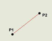
Rubber Band Line & Cross Hairs With the Line command you can draw a simple line from one point to another. When you pick the first point and move the cross-hairs to the location of the second point you will see a rubber band line which shows you where the line will be drawn when the second point is picked. Line objects have two ends (the first point and the last point). You can continue picking points and AutoCAD will draw a straight line between each picked point and the previous point. Each line segment drawn is a separate object and can be moved or erased as required. To end this command, just hit the Return key on the keyboard.
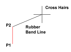
The Line Object

Command Sequence

Command: LINE
Specify first point: (pick P1)
Specify next point or [Undo]: (pick P2)
Specify next point or [Undo]: Return (to end)

You can also draw lines by entering the co-ordinates of their end points at the command prompt rather than picking their position from the screen. This enables you to draw lines that are off screen, should you want to.

The Construction Line Command

Toolbar Draw Construction Line
Pull-down DrawConstruction Line
Keyboard XLINE short-cut XL

The Construction Line command creates a line of infinite length which passes through two picked points. Construction lines are very useful for creating construction frameworks or grids within which to design.

Construction lines are not normally used as objects in finished drawings, it is usual, therefore, to draw all your construction lines on a separate layer which will be turned off or frozen prior to printing. See the Object Properties tutorial to find out how to create new layers. Because of their nature, the Zoom Extents command option ignores construction lines.

Command Sequence

Command: XLINE
Specify a point or [Hor/Ver/Ang/Bisect/Offset]: (pick a point)
Specify through point: (pick a second point)
Specify through point: Return (to end or pick another point)

You may notice that there are a number of options with this command. For example, the "Hor" and "Ver" options can be used to draw construction lines that are truly horizontal or vertical. In both these cases, only a single pick point is required because the direction of the line is predetermined. To use a command option, simply enter the capitalised part of the option name at the command prompt. Follow the command sequence below to see how you would draw a construction line using the Horizontal option.

Command Sequence

Command: XLINE
Hor/Ver/Ang/Bisect/Offset/: HReturn
Through point: (pick a point to position the line)
Through point: Return (to end or pick a point for another horizontal line)


The Ray Command
Toolbar custom Ray
Pull-down DrawRay
Keyboard RAY

The Ray command creates a line similar to a construction line except that it extends infinitely in only one direction from the first pick point. The direction of the Ray is determined by the position of the second pick point.

Command Sequence
Command: RAY
Specify start point: (pick the start point)
Specify through point: (pick a second point to determine direction)
Specify through point: Return (to end or pick another point)

The Polyline Family

Polylines differ from lines in that they are more complex objects. A single polyline can be composed of a number of straight-line or arc segments. Polylines can also be given line widths to make them appear solid. The illustration below shows a number of polylines to give you an idea of the flexibility of this type of line.


You may be wondering, if Polylines are so useful, why bother using ordinary lines at all? There are a number of answers to this question. The most frequently given answer is that because of their complexity, polylines use up more disk space than the equivalent line. As it is desirable to keep file sizes as small as possible, it is a good idea to use lines rather than polylines unless you have a particular requirement. You will also find, as you work with AutoCAD that lines and polylines are operationally different. Sometimes it is easier to work with polylines for certain tasks and at other times lines are best. You will quickly learn the pros and cons of these two sorts of line when you begin drawing with AutoCAD.

The Polyline Command

Toolbar Draw Polyline
Pull-down DrawPolyline
Keyboard PLINE short-cut PL

The Polyline or Pline command is similar to the line command except that the resulting object may be composed of a number of segments which form a single object. In addition to the two ends a polyline is said to have vertices (singular vertex) where intermediate line segments join. In practice the Polyline command works in the same way as the Line command allowing you to pick as many points as you like. Again, just hit Return to end. As with the Line command, you also have the option to automatically close a polyline end to end. To do this, type C to use the close option instead of hitting Return. Follow the command sequence below to see how this works.

Command Sequence

Command: PLINE
Specify start point: (pick P1)
Current line-width is 0.0000
Specify next point or [Arc/Halfwidth/Length/Undo/Width]:
(pick P2)
Specify next point or [Arc/Close/Halfwidth/Length/Undo/Width]: (pick P3)
Specify next point or [Arc/Close/Halfwidth/Length/Undo/Width]: (pick P4)
Specify next point or [Arc/Close/Halfwidth/Length/Undo/Width]: (pick P5)
Specify next point or [Arc/Close/Halfwidth/Length/Undo/Width]: Return (or C to close)

In the illustration on the right, the figure on the left was created by hitting the Return key after the fifth point was picked. The figure on the right demonstrates the effect of using the Close option.

It is worth while taking some time to familiarise yourself with the Polyline command as it is an extremely useful command to know. Try experimenting with options such as Arc and Width and see if you can create polylines like the ones in the illustration above. The Undo option is particularly useful. This allows you to unpick polyline vertices, one at a time so that you can easily correct mistakes.

Polylines can be edited after they are created to, for example, change their width. You can do this using the PEDIT command, ModifyObjectPolyline from the pull-down menu.


Jan 19, 2008

Using Co-ordinates

Introduction

A good understanding of how co-ordinates work in AutoCAD is absolutely crucial if you are to make the best use of the program. If you are not familiar with co-ordinates and co-ordinate systems, take some time to familiarise yourself with the basic concepts.

Co-ordinates fall into two types, namely Cartesian and Polar. A basic understanding of these co-ordinate types will help you to use AutoCAD to construct drawings more easily. In addition, these two co-ordinate types come in two distinct flavours. They can be either Absolute or Relative. Knowing just when and where to use the various types and flavours of co-ordinate is the key to efficient drawing with AutoCAD.


Cartesian Co-ordinates

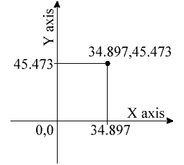
Despite the fancy title (named after the French philosopher and mathematician René Descartes 1596-1650), the Cartesian co-ordinate system is the standard co-ordinate system. The position of a point can be described by its distance from two axes, X and Y. This results in a simple point description using two numbers separated by a comma e.g. 34.897,45.473.

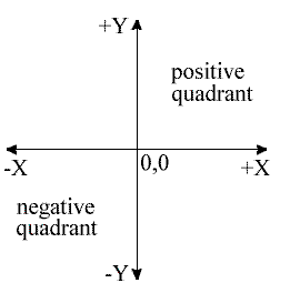
In the example on the right the point described lies 34.897 drawing units to the right of the Y axis and 45.473 drawing units above the X axis. The first value (34.897) is known as the X co-ordinate because it's value is measured along the X axis. The second value is known as the Y co-ordinate because it's value is measured along the Y axis. The X and Y axes are two lines of infinite length which intersect at the origin point. The co-ordinate value of the origin point is always 0,0. When viewed in plan the X and Y axes are always perpendicular to one another with the X axis in a horizontal position and the Y axis in a vertical position (See illustration). X co-ordinate values become negative to the left of the Y axis and Y co-ordinate values become negative below the X axis. All co-ordinate values (both X and Y) are negative in the lower left hand quadrant and positive in the upper right hand quadrant. Normally we try to work in the positive quadrant. Although this is not essential for AutoCAD to operate, it does tend to make life easier because we don't need to worry about negative numbers.

AutoCAD allows you to use co-ordinates to draw objects rather than using pick points. For example you could draw a line like this:
Command Sequence

Command: LINE

From point: 34.897,45.473
To point: 54.896,65.395
To point: Return (to end)

This sequence draws a line between the two co-ordinate points specified. Note that if you enter a co-ordinate that is off the screen the line will still be drawn to the required point. You will then need to zoom out in order to see the whole line. You can also start the Line command by clicking Line on the Draw toolbar or from the pull-down menu (DrawLine).


Polar Co-ordinates

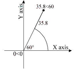
Polar co-ordinates achieve the same result i.e. the description of the position of a point. The main difference is that polar co-ordinates use one distance and one angle to describe the position of a point rather than the two distances in the Cartesian system. The distance and angle measurements are made relative to an origin. This results in a point description which looks like this 34.897<30 style="font-weight: bold;">


The UCS Icon

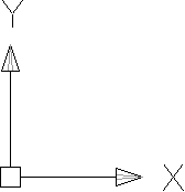
In the bottom left hand corner of the AutoCAD drawing window you will see a symbol like the one shown on the right. This is called the UCS (User Co-ordinate System) icon and it is there to remind you which is the X axis and which is the Y axis. The empty box at the intersection of the X and Y axes is there to remind you that you are using "World" co-ordinates and that the UCS icon is not positioned over the true origin of the current co-ordinate system, probably because it is off screen.


Absolute & Relative Co-ordinates

Both Cartesian and polar co-ordinates come in two flavours, absolute and relative. The distinction is quite simple, absolute co-ordinates relate to the X and Y axes and the origin of the current co-ordinate system, whilst relative co-ordinates relate to the current pick point. When you are specifying co-ordinates you need to tell AutoCAD which type you want. Absolute co-ordinates are typed exactly as in the examples above. To specify a relative co-ordinate you need to use the "at" symbol as a prefix. In the case of the two examples above a relative Cartesian co-ordinate looks like this @34.897,45.473 and a relative polar co-ordinate looks like this @34.897<30. style="font-weight: bold;">

Command: LINE
From point: 30,40 (an absolute Cartesian co-ordinate)
To point: @0,12 (a relative Cartesian co-ordinate)
To point: @12<0>
To point: @0,-12 (another relative Cartesian co-ordinate)
To point: C (to close)

Try this sequence out and watch the square drawn as you enter each co-ordinate value. You can also use this method to quickly draw a rectangle of known size. Say you needed to draw a rectangle 20 drawing units wide and 10 drawing units high and you didn't mind where exactly the rectangle is drawn, you could do this:
Command Sequence


Command: RECTANGLE
Specify first corner point or [Chamfer/Elevation/Fillet/Thickness/Width]: (pick a point near the middle of the drawing area)
Specify other corner point or [Dimensions]: @20,10

Note that the relative X co-ordinate determines the rectangle width and the relative Y co-ordinate determines the rectangle height.


The Status Bar

Co-ordinates The status bar at the bottom of the AutoCAD window always shows the current co-ordinate value at the cursor point. Watch the co-ordinate values change as the cursor moves across the drawing area. You can turn the dynamic co-ordinate display off and on using the F6 key on the keyboard.

Jan 14, 2008

Creating Lights, Cameras & Rendered Images in AutoCAD

In this tutorial you learn how to create lights and cameras in your drawings, and how to render images of your 3D geometry. You'll find these skills very useful for creating presentation graphics.


Topics covered include:

  • Creating lights.
  • Creating cameras.
  • Rendering images.
By the time you complete this tutorial you should feel rendering images of most 3D geometry.

Creating 3D Doors and Windows with Solids Modeling Tools

In this lesson you learn how to create 3D doors and windows from elevations. These solid modeling techniques can be used to create walls from elevations as well.

You will find the techniques demonstrated in this project extremely useful if you need to be able to create 3D models for rendering in AutoCAD, Autodesk VIZ or 3DS MAX.


Topics covered in this project include:

  • Converting Elevation Geometry into 3D Solid Geometry
  • Creating 3D Blocks
  • Defining User Coordinate Systems with the UCS Command
  • Inserting 3D Blocks into Wall Gaps
By the time you complete this project you should have the skills you need to turn any elevation into a 3D component, and to place that component at any orientation in a 3D drawing.

Flattening 3D Geometry into 2D Geometry You Can Edit

In this project you learn how to flatten a perspective view of a model, then edit it using standard AutoCAD 2D editing commands.


You learn how to:

* Display hidden lines in 3D models in a hidden linetype.
* Delete or otherwise modify geometry in orthogonal and non-orthogonal views of 3D models.
* Use the BHATCH command to fill areas in a view with hatch patterns or solid colors.

By the time you complete this project you will have the skills required to "flatten" almost any 3D object into 2D views you can edit, paint or export for use in other applications.

Creating 3D Architectural Models Fast

Creating 3D Architectural Models Fast

In this project you master the most traditional approach to creating 3D buildings. Specifically, you learn how to start with a 2D floor plan and change the thickness of the wall lines to push them into the third dimension.

This method of creating three-dimensional walls is quick, requires little drawing preparation, and yields walls you can hide, shade and apply materials to.

You learn how to:

* Change the Thickness of an 2D Object to make it Three Dimensional
* Change the Elevation of an object to position it above the current drawing plane.
* Use the REGION command to create opaque planes in a 3D mode.
* Remove hidden lines from a perspective view of a 3D object.
* Quickly create 2D Elevations from 3D objects.
* Define a user coordinate system, or drawing plane, by selecting three points on an object.
* Move objects from one user coordinate system to another.

Instructions for plotting hidden and shaded views of 3D models appear in other Complete Support tutorials.

Creating Plot Style Tables

Installing Plotters & Creating Plot Style Tables

Every AutoCAD user needs to setup a plotter and configure its use of plot styles sooner or later.


You learn how to:

* Install a plotter.
* Configure a plot style table to use different pens.

By the time you complete this tutorial you should feel comfortable installing most plotters and configuring most plot style tables.

Plot Drawings to Scale

How to Create & Plot Drawings to Scale

Over the years, Autodesk has designed AutoCAD to support a variety of layout methodologies. In this tutorial you become familiar with most of them. You also learn how to:


* Create scaled drawings you can plot.
* Create template files that will reduce drawing setup time.
* Convert drawings created using old layout methods to using the newer, more flexible Model Space/Paper Space tool set.

It's important to understand the evolution of drawing layout methods for several reasons.

* If you work with old drawing files, they may have been laid out using an old method and you may have to update them to use model space and paper space.

* If your office is upgrading from very early versions of AutoCAD, chances are good that you won't be using layouts or paper space to layout drawings currently. Your design/drafting team has to decide if you will begin using the new tools, or teach every new employee how to layout drawings the way you do now.

* If you go to work for another company, chances are good that they will use layouts to create plottable drawings. To maximize your employability, you need to master the new tools.

When AutoCAD was first released, Autodesk asked users to create giant borders and title blocks around objects drawn at real world scales. For example, you might draw a football stadium, then create a title block roughly 600' x 384' around the football stadium, with letters more than 8' tall. When you plotted the drawing you would specify the relationship between units in the drawing and units on the printed page. For example, you might say that 1" plotted was equal to 16' feet in the drawing. This would plot the drawing at 1/16"=1'.

In later releases, Autodesk introduced model space and paper space. In effect, every AutoCAD drawing came with two drawing environments. You would create your objects at full size in model space. Then you would move into paper space, where you would draw your border and title block at full size. You might have a football stadium in model space, but in paper space you would have a 36"x24" piece of paper. You would "cut holes" in paper space to let views of the geometry in model space show through. This let users plot drawings that showed multiple views of their objects at a variety of scales. On the other hand, you couldn't create multiple "paper spaces" showing multiple layouts in a single drawing file. Many users also found the large number of commands you had to use to layout a drawing awkward.

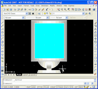
In AutoCAD 2000 and later releases, users were allowed to have multiple "paper spaces" (called layouts) in their drawings. This lets you plot several sheets based on a single AutoCAD drawing file. The following image shows geometry created in model space displayed within a title block residing on a layout.

It is important to note that applications like Architectural Desktop now use layouts to display different views of your models. For example, one layout might display a top view and a 3D isometric view while another might display a reflected ceiling plan. Selecting a layout displays the related views.

Dimensioning Smarter with Associative Dimensions

In this project you learn how to dimension objects with associative dimensions. Unlike standard dimensions, which must be recreated, edited along with objects in order to accurately reflect geometric values, associative dimensions automatically update when the geometry they measure changes. This insures that dimensions are always accurate.

Not all drawing offices use associative dimensions because they are incompatible with AutoCAD versions before AutoCAD 2002. Nevertheless, your office may wish to consider updating its drawing standards include the use of associative dimensions because they really can save you a great deal of time and effort. You will find they practically eliminate the use of the dimension scale factor (DIMSCALE) and dimension factors (DIMLFAC) which are a constant source of hassle for many offices.


In this tutorial you learn how to:

* Make AutoCAD create associative dimensions.
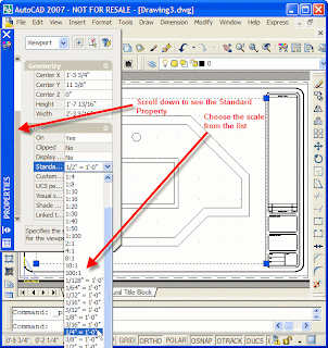
* Create a scaled viewport in a layout.
* Dimension objects displayed in a layout.
* Change dimensioned objects.

By the time you complete this project you should feel comfortable working with associative dimensions.

Scaling & Overriding Dimensions

In this project you master the skills required to scale dimensions created in model space using Dimension Styles. This lets you insure they plot correctly in paper space. You also learn how to create "exceptions" to Dimension Style rules.


You learn how to:

* Control the scale of dimensions created in model space
* Create dimension overrides

Tip:
You can dimension geometry created in model space in paper space which makes scaling dimensions in a multiview drawing much easier. Those skills are covered in another tutorial.

Creating Dimensions & Dimension

In this project you master the skills required to create dimension styles in your drawings. Dimension styles control the appearance of your dimensions. Changes you make to a dimension style will affect all the dimensions that depend upon that style. By the time you have completed this project, you should have the skills required to create your own dimensions styles.


You learn how to:

* Create dimension styles
* Create dimensions based on dimension styles
* Modify dimension styles to change dimension appearance
* Control dimensions using dimension families
* Use the DesignCenter Palette to copy dimension styles between drawings

By the time you complete this project you should feel comfortable changing the appearance of dimensions in most AutoCAD drawings.

Inserting Blocks From One Drawing

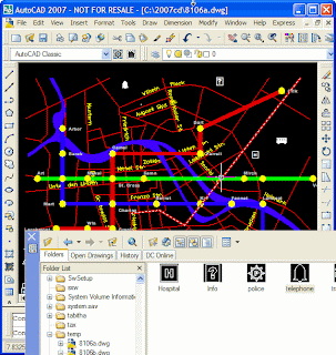
AutoCAD features many tools which make it easy to bring data from one drawing into another. In this tutorial you master the skills to mine data, moving blocks, text styles, and other data from drawing to drawing.


You learn how to:

* Display the DesignCenter palette
* Use the DesignCenter palette to externally reference (xref) one drawing into another
* Use the DesignCenter palette to insert blocks from one drawing into another.
* Use the DesignCenter palette to create a new tool palette that contains a set of blocks.

By the time you complete this tutorial you should be able to move design geometry between drawings with ease and efficiency.

Creating & Placing Blocks

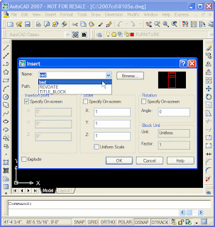
In this tutorial you create and place symbols, called blocks, in a drawing.


You learn how to:

* Create blocks.
* Identify the base point for a block.
* Place blocks in a drawing.
* Edit blocks.
* Export a block to its own drawing file.

By the time you complete this series of lessons you should feel comfortable working with blocks.

Creating & Using Layers

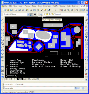
In this tutorial you master the skills required to create and use layers.


You will learn how to:

* Create a new layer
* Draw on a layer
* Move objects of a given type to that layer
* Assign colors and linetypes to layers
* Display and hide layers
* Save layer states to make displaying or hiding groups of layers easy

This chapter delivers important skills required by every AutoCAD user.

Drawing & Editing Design Geometry

In this tutorial you master the skills required to setup a scaled drawing. You also learn how to begin to draw with speed and precision.


You learn how to:

* Specify the units in which you want to work.
* Determine the size of your drawing area.
* Draw lines of specific lengths.
* Draw lines at specific angles.
* Clean up line intersections.
* Draw circles.
* Delete objects.
* Display scaled views of your design geometry on a drawing sheet.

All AutoCAD-based designers need these skills in order to create scaled construction or manufacturing documents for others to use.

start creating drawings

In this tutorial you master the skills you need to start creating drawings with AutoCAD.

You learn how to:

* Launch AutoCAD.
* Start a new drawing.
* Specify the size of your drawing sheet.
* Start drawing objects.
* Save a drawing file.
* Exit AutoCAD.

This is a great project for new AutoCAD users who need a bit of help with basic computer skills. Those who want to become comfortable with the new AutoCAD user interface will also find it interesting.

AutoCAD Shortcut Keys

CTRL+A - Selects ALL objects in drawing
CTRL+B - Toggles Snap
CTRL+C - Copies objects to Clipboard
CTRL+D - Toggles coordinate display
CTRL+E - Cycles through isometric planes
CTRL+F - Toggles running object snaps
CTRL+G - Toggles Grid
CTRL+H - Toggles PICKSTYLE on/off
CTRL+J - Executes last command
CTRL+L - Toggles Ortho mode
CTRL+N - Creates a new drawing
CTRL+O - Opens existing drawing
CTRL+P - Prints current drawing
CTRL+R - Cycles layout viewports
CTRL+S - Saves current drawing
CTRL+T - Toggles Tablet mode
CTRL+V - Pastes data from Clipboard
CTRL+X - Cuts objects to Clipboard
CTRL+Y - Repeats last action
CTRL+Z - Reverses last action
CTRL+[ - Cancels current command - forget this - use escape key
CTRL+\ - Cancels current command - forget this - use escape key
F1 - Displays Help
F2 - Toggles text window on/off
F3 - Toggles OSNAP
F4 - Toggles TABMODE
F5 - Toggles ISOPLANE
F6 - Toggles COORDS
F7 - Toggles GRIDMODE
F8 - Toggles ORTHOMODE
F9 - Toggles SNAPMODE
CTRL+0 - Clean Screen
CTRL+1 - Properties
CTRL+2 - Design Center
CTRL+3 - Tool Palettes Window
CTRL+4 - Sheet Set Manager
CTRL+5 - Info Palette
CTRL+6 - dbConnect
CTRL+7 - Markup Set Manager
CTRL+8 - QuickCalc
CTRL+9 - Command Line
Acad2004/2005/2006 default Combo Short-cuts
Google Groups
Subscribe to design helper
Email:
Visit this group